


80-CHARACTER SERIAL LCD ANNUNCIATOR 315-080
|
Add to My Constguide favorites
 80-CHARACTER SERIAL LCD ANNUNCIATOR 315-080
|
Description
• AC Power • Listed to UL Standard 864, 9th Edition • Powering the devices on the Repeater-Bus from auxiliary power supply The Repeater-Bus can be powered by an auxiliary power supply when the maximum number of Repeater-Bus devices exceeds the Repeater-Bus power requirements. See the FACP manual for more information. • Wire Requirements: Power Circuit – 14 to 18 AWG (0.75 – 2.08 mm2) wire for 24 VDC power circuit is acceptable. Power wire distance limitation is set by 1.2 volt maximum line drop form source to end of circuit. – All connections are power-limited and supervised. – Agency Listings and Approvals Ordering OptionsControls and Indicators
• Alarm
• Supervisory
• Alarm Silenced
• TroubleControls and Indicators
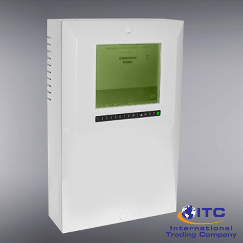
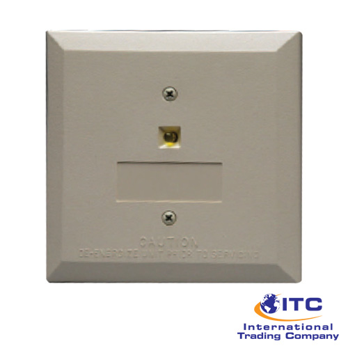
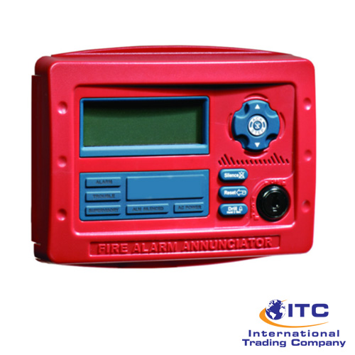
• Backlit 80-character LCD display(20 characters x 4 lines)
• Mimics all display information from the host panel
• Control switches for System Acknowledge, Signal Silence, and Reset
• Control switches can be independently enabled or disabled at the FACP
• Keyswitch enables/disables control switches and mechanically locks annunciator enclosure
• Keyswitch can be enabled or disabled at the FACP
• Enclosure supervised for tamper
• System status LEDs for AC Power, Alarm, Trouble, Supervisory, and Alarm Silence
• Local sounder can be enabled or disabled at the FACP
• 315-080 connects to the Repeater-Bus terminal on the FACP and requires minimal panel programming
• Displays device type identifiers, individual point alarm, trouble, supervisory, zone, and custom alpha labels
• Time and date display field
• Surface mount directly to wall or to single, double, or 4” square electrical box
• Semi-flush mount to single, double, or 4” square electrical box. Use ANNSB80KIT for angled view mounting
• Can be remotely located up to 6,000 feet (1,800 m) from the panel
• Backlight turns off during AC loss to conserve battery power but will turn back on if an alarm condition occurs
• May be powered by 24 VDC from the host FACP or by remote power supply (requires 24 VDC)
• Up to eight 315-080 repeaters can be connected on the RS485 Repeater-Bus 80-Character Serial LCDThe Repeater-Bus:
• Repeater-Bus Devic e Addressing Each Repeater-Bus device requires a unique address (ID Number) in order to communicate with the FACP. A maximum of 8 devices can be connected to the FACP Repeater-Bus communication circuit. See the FACP manual for more information.
• Wire Requirements: Communications Circuit The 315-080 connects to the FACP Repeater-Bus communications cir-cuit. To determine the type of wire and the maximum wiring distance that can be used with FACP Repeater-Bus accessory modules, it is necessaryto calculate the total worst case current draw for all modules on a single 4-conductor bus. The total worst case current draw is calculated by adding the individual worst case currents for each module
A maximum of eight 315-080 repeater modules may be connected to this circuit.
The listings and approvals below apply to the 315- 040. n some cases, certain modules may not be listed by certain approval agen-cies, or listing may be in process. Consult factory for latest listing status.
• UL Listed: S36108
• 315-080: Red 80 character LCD Annunciator